|
|
|
 |
 |
 |
 |
 |
 |
 |
 |
Spring 2000
Computer Science 3410 - Tutorials
Binary Addition
|
|
 |
|
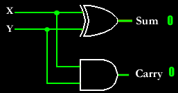
This is a combinational circuit that performs the addition of two bits (the augend and the addend). It is called a half-adder. There are two outputs because an addition results in a sum and possibly a carry. However, this circuit cannot do the entire job. In normal addition, it is customary to add two digits and then possibly a carry. The full-adder below does exactly that. |
|
|
|
 |
| |
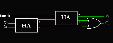
The full-adder shown above performs the arithmetic sum of three input bits. Two of the input variables denote the two significant bits to be added. The third input represents the carry from the previous lower significant position. The full adder can built with two half-adders. The half-adder is represented with a block diagram with a "HA" on it. Below is a truth table for the FA (full-adder) circuit.
| X |
Y |
Ci |
| |
C0 |
S |
| 0 |
0 |
0 |
| |
0 |
0 |
| 0 |
0 |
1 |
| |
0 |
1 |
| 0 |
1 |
0 |
| |
0 |
1 |
| 0 |
1 |
1 |
| |
1 |
0 |
| 1 |
0 |
0 |
| |
0 |
1 |
| 1 |
0 |
1 |
| |
1 |
0 |
| 1 |
1 |
0 |
| |
1 |
0 |
| 1 |
1 |
1 |
| |
1 |
1 |
|
|
|
|
 |
 |
 |
 |
 |
 |
 |
 |
|
|

