|
Experiments |
|
|
|
||
|
Experiment No. 8: Finite-State Machines Objective |
|||||||||||||||||||||
|
Finite-state machines are a general class of circuits in which the outputs depend on the past behavior of the circuit, as well as on the present values of inputs. In this experiment, we shall apply the concept of the finite-state machine and design a stop light. |
|||||||||||||||||||||
|
Discussion |
|||||||||||||||||||||
|
Small Town, Texas has heard that University of Houston Digital Logic students are efficient circuit designers. Therefore, they are hiring you to design a stop light for their only intersection. The intersection runs both north/south and east/west. You, with your computer scientist's love of abstraction, will view this stop-light as a finite-state machine. It has memory, and it has transitions from one state to another based upon input values and the previous state. First, let's look at a table which describes the different states of this
stop-light:
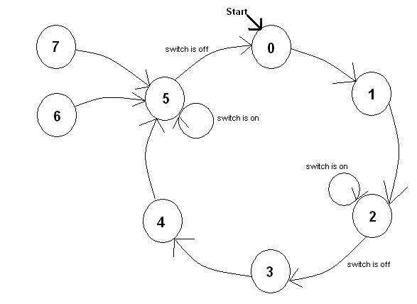
As you can see in the table, there are six different states. There is a safety interval where both lights are red (states 2 and 5). We can view this stop light as a finite-state machine with a state diagram. Each state is represented by a circle. The transitions follow the arrows. This transition can be defined by a Boolean expression which we call the transition function.
Notice that this looks similar to the state diagram for a three-bit counter except for an important difference. Our stop light, and thus our state diagram, uses only six states. It takes three bits to represent the binary value for each state. With three bits, we can represent up to eight states. Two states are not used. Nevertheless, you must include these state in your diagram. You need to be sure that if you get stuck in one of these states, you can get out. State five is a good state to go to since both lights will be red in state five. Here's the tricky part of the assignment. The mayor of Small Town has
suggested that you build something to put the light into a red/red
combination in case of emergency. We will pretend that it is a pushbutton. If
the button is pressed, the next time the light arrives in a red/red state it
will stop cycling until the button is pressed again. It must cycle through
its green or yellow states as normal before arriving at the red/red state.
Here's an example. The light is in state three. The north-south signal is red
and the east-west signal is green. The traffic officer pushes the button
while the light is in state three. The light will continue as normal to state
four, a red/yellow state. It will then arrive at state five where it will
remain until the button is pressed again. This is going to require memory. |
|||||||||||||||||||||
|
Prelab |
|||||||||||||||||||||
|
Since our machine differs from a counter, we will need to design it from scratch. We start with a truth table. It takes three bits to represent our machine which goes through the states 000, 001, 010, 011, 100, and 101. We will also need to take care of 110 and 111, since our machine may end up there by program error. We will use the variables A, B, and C as the variables whose binary value will represent the state. We will use the variable D to hold the value of the pushbutton when it is pressed. From the truth table, find the combinational circuits which will define
A(t+1), B(t+1), C(t+1), and D(t+1). The easiest way to do this is to use
Karnaugh maps. You can find Karnaugh maps prepared for this lab here. |
|||||||||||||||||||||
|
Procedure |
|||||||||||||||||||||
|
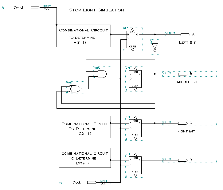
We will use four D flip-flops as our memory elements (don't let the variable D and D flip-flop confuse you). Recall that the output of a D flip-flop will be whatever the data input was. See your textbook if you don't know how a D flip-flop works. In the schematic which follows, you will notice that I have already built the combinational circuit which defines B(t+1). You will now need to build the circuit which defines the other three memory elements. As I have mentioned on the K-map page, there will be an XOR relation between the Switch and the output of the D flip-flop for some of the combinational circuits. You can leave the PRN and CLRN inputs to the flip-flop alone. The software normally starts the simulation with all flip-flops reset.
When you have completed you circuit, set up a waveform which allows you to
run through a couple of cycles. I used a grid size of 10.0ns and an end time
of 320.ns. You will need to turn in your circuit (call it stoplight.gdf)
and a waveform (call it stoplight.scf) which clearly shows that your
circuit performs according to specifications. Click here
for some sample waveforms. |
|||||||||||||||||||||
|
What to turn in |
|||||||||||||||||||||
|

